Thursday, December 5, 2019

What is Power Over Ethernet (PoE) Media Converter where is has been using.

It is often the case that media converter is deployed to connect copper to fiber, enabling network managers to overcome transmission distance limitation of traditional copper cabling. As one type of fiber media converter, the PoE media converter also works in those situations. How much do you know about the PoE media converter? How to use it? This article intends to explain the basis of the PoE media converter to help you learn more about it.

What Is a PoE Media Converter?

Traditionally, fiber media converters can only transmit data; while PoE media converter can not only help users to create an Ethernet-fiber link but also act as a power sourcing equipment (PSE) device to provide power to one or two powered devices (PD) over the UTP network cable.
By using the PoE media converter like the 10/100/1000M PoE media converter shown below, it provides a flexible and cost-effective solution for implementing and optimizing fiber links. In addition, PoE media converters like all the other Ethernet media converters, breaking the distance limitation of Ethernet cables, extend the network distance via fiber to remote PD such as the original VoIP phones, wireless access points, security cameras, and point-of-sale (POS) terminals in temperature control systems, and even in-flight entertainment systems.
poe-media-converter.jpg

How Does a PoE Media Converter Work?

There are two applications in which PoE media converter works: the PoE media converter only delivers data or it delivers both data and power. The picture below shows how the PoE media converter provides fiber-to-copper connections between the fiber switch and wireless access point and powers the access point simultaneously.
The fiber is run for a long distance to the PoE media converter located near a convenient AC or DC power source, where it does the fiber-to-copper conversion. At the other end of the UTP cable is the wireless access point, located up to 100 meters away from the PoE media converter.
PoE media converter applications.jpg

How to Use a PoE Media Converter

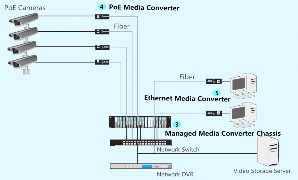
There are three main applications of PoE media converters: fiber to IP cameras, fiber to wireless access points, and fiber to the desktop. Here we take fiber to IP cameras as an example to show the application of PoE media converter.
Before starting the deployment process, make sure you have access to the following devices: a Gigabit fiber switch, a 10/100/1000M PoE media converter, an IP camera, a network cable (like Cat5e/Cat6), a fiber patch cable (like OS2/OM4), and two SFP fiber optic transceivers.
Step 1: Insert an SFP module into the fiber port of the PoE media converter and an SFP module into the SFP port of the switch.
Step 2: Connect a fiber optic cable to the SFP module on the PoE media converter and the other end of the cable into the switch.
Step 3: Connect the RJ45 ports of the PoE media converter and the IP camera using a UTP Ethernet cable.
The video below will help you to get a better understanding of PoE media converters.

PoE Media Converter Buying Guide

How to choose the best PoE media converter that suits your network requirement? There are some points you should consider.
Data rate: the data rate of the PoE media converter is the first thing that should be considered. There are 10M, 100M, 1000M, 10/100M, and 10/100/1000M PoE media converters in the market which can be chosen as you need.
Port number and port type: in most cases, a PoE media converter features one fiber port and one RJ45 port, but there are still some PoE media converters that have multiple ports such as one or two fiber ports and four RJ45 ports.
Single mode or multimode: according to the transmission media, the PoE media converter can be divided into single mode converter and multimode converter, which will affect the transmission distance and the fiber optic transceivers that can be used.
Duplex mode: as some PoE media converters can only be used as full duplex but not half duplex, packet loss may occur when it is connected with the switch or hub that supports half duplex. So make sure it supports full duplex and half duplex.
Operating temperature: it should be noted especially when you need an industrial PoE media converter. Remember to check the operating temperature of the media converter to see if it can operate under extended temperature (−40 °C to 125 °C).
Standards: generally PoE media converter are IEEE802.3af, IEEE802.3at, or IEEE802.3bt compliant. Confirm that the PoE media converter you want supports these standards or there may be some compatibility problems.


What is CCTV Media Converter

Video Security and Surveillance Network Design With Media Converters


In Market Media converters are simple and flexible devices coming into various types, which work on the physical layer of the network to provide a simple way to convert one media type into another. The most commonly utilized functions of media converters are distance extension by transmitting one type of signal into single-mode fiber, or introducing fiber optic cabling in the existing copper-based network without making other change. It is an ideal solution to save more money and manpower or time to upgrade networks. Media converter can be installed almost everywhere in a network, which makes it a popular choice. What’s more, media converters that available on the market are being designed to perform many other functions. Video security and surveillance system is one of the fields widely using media converters. This post will offer details solutions about how to use fiber optic media converter for cctv cameras network.

Video Security and Surveillance Network Introduction

Video security and surveillance are necessary and closely related to most industries and daily life nowadays. Cameras are almost everywhere in our cities and towns, which provide great benefits for corporate and government. Many types of video security and surveillance networks that are designed for applications in different environments. Analog video network and IP video network are the two most commonly used types for security and surveillance video transmission. The former one is invented before the latter one and is a cost-effective solution for video surveillance in small area with analog closed circuit television (CCTV) cameras. It is also a good choice for video security at home.
While IP video is more advance and can provide better image quality and network performance in large scale. The biggest character of IP video surveillance network is that every camera has its own IP address to tell itself from the others in the whole video network. Currently, with the demand for higher transmission speed, image quality and longer transmission distances, fiber optic cables are widely used in the video network. Thus, in both of the two surveillance networks, media conversion are necessary, like conversions between fiber and copper or video to fiber. The following will offer the cabling solutions that using fiber optic media converter for cctv.
fiber optic media converter for cctv

Analog Video Network Cabling Infrastructure

In a typical analog video network (shown in the above picture), analog CCTV cameras are connected to a central management room or devices (VCR—video cassette recorder or DVR—digital video recorder) via coaxial cables. If the camera has PTZ (Pan-Tilt-Zoom) function, an additional controller is added.
As mentioned, the performance and the transmission distance are limited by using copper cables. To connector more fixed analog cameras and PTZ analog cameras, fiber optic cable should be introduced to this typical network. Then fiber media converters are the best solutions. The following picture shows the basic structure or an upgraded version of a typical analog video structure which using fiber optic cable in this network.
fiber optic media converter for cctv
To connect the fixed analog cameras to the server room, a pair of fiber media converters should be added between the server room and cameras. Video signals will be transmitted into fiber optic signals. For analog PTZ cameras, there are two types of signals should be converted into fiber optic signals, one for video and one for data. Thus, two different media converters or a fiber media converter that covers the two functions should be installed.
It is known that fiber media converters should be used in pairs. As one of the media converters is in deploy on the fiber end that near the camera, the other one should be deploy on the other fiber ends that near the server room. For better management, all the fiber media converters at the fiber end near the server room could be installed in a managed fiber media converter rack chassis.
fiber optic media converter for cctv

IP Video Network Cabling Infrastructure

In a typical IP video surveillance network (shown in the above picture), IP cameras are connected directly to the local area network and transport video across the IP network via UTP cabling and switches. PoE IP cameras are also time-save and cost-effect solutions. Video can be recorded to any PC or server on the network. To introduce fiber optic cabling in to this typical IP video network, the method is similar to introducing fiber optic into an analog video network as described in the above paragraph.
In the following case (shown in the following picture), PoE IP cameras are used. A pair of PoE media converters should be installed on both ends of a length of fiber optic cable to achieve the conversion between video and fiber. At the computer side where the videos are recorded, a pair of Ethernet media converters should be installed. All of the fiber optic media converter for cctv near the network switches can be set at a managed media converter chassis before the connected to the switches.
fiber optic media converter for cctv

Video Security and Surveillance Network Solution

The following chart list the related fiber optic media converter for cctv required for analog video and IP video security and surveillance network. The numbers in the following table are highlighted in the above pictures and represent the corresponding devices. Kindly contact Ashish9224@gmail.com for more details.
NumberProduct
1Fiber Video Converters
2RS-485/RS-232 Converter
3Managed Fiber Media Converter Chassis
4PoE Media Converter
5Ethernet Media Converter

Thursday, May 17, 2018

Helping You Understand & Improve Your CCTV System Quality

Your CCTV system is an expense you don’t really want, so make sure you know what you need.

Lets spend some time making sure your CCTV system design is right and you get the best results possible for your money. Understanding what you want to achieve is the first and most over looked step.

What do you want to achieve?

You have 4 main choices that each camera in your surveillance system is to be used for. By understanding what you want to achieve from the camera system will determine how many cameras you will need.

The 4 main uses of security cameras are:

  • DETECT what a person is doing
  • OBSERVE what is happening in a scene

Each of these is applied differently depending on your type of premises.

  • Business CCTV
  • Home CCTV
  • Industrial CCTV

Improving a CCTV System Design in 7 Steps

Many people design their CCTV system in the wrong order. They buy some cameras first, then a recorder and install them before realising the system is not performing as expected.

Follow theses 7 steps and I can assure you that the results will be much better and possibly at a lower cost.

Step 1. Determine what your want to protect

This will help you to understand what to expect from the surveillance cameras

Step 2. How will the system be used

How will you use the CCTV system most of the time?
    • Live viewing from a back office
    • Different front and back office views
    • Off site live viewing
    • Only looked at when something has happened

Step 3. Define the time frame before you will know something has occurred

Understanding what events you are looking for will give an indication of how long you need to store the recordings for at a minimum and the type of storage device you will need.
    • Monitoring staff theft – 14 days
    • Shoplifting – 7 days
    • Home surveillance including short holidays – 14 days
    • Public areas – 30 to 90 days
    • Slip & trip incidents – 30 to 90 days

Step 4. Identify camera locations and lens sizes

Depending on the answers to step 1, you may need to mount the cameras low or a long way back, which will determine the lens size, camera resolution and special lighting features. Good surveillance camera placement will make the biggest impact to your results

Step 5. Select the camera style

Now that you know where each camera will be located and its intended application, you can work on what camera style will work best in each location
    • Do not use standard dome cameras for the following situations
      • If the lens focal length is greater than 12mm
      • if the light is greatly varying
      • Instead buy a camera with a separate lens
    • Is megapixel required?
    • Will lighting be sufficient at night?
    • Should a vandal resistant camera be used?
    • Can rain or sun hit the camera? Check the IP rating

Step 6. Choose the recording and storage medium

By now you should know if you are installing surveillance cameras that are analogue or IP CCTV connection. This will determine if you need a DVR (digital video recorder), NVR (network video recorder) or a hybrid recorder
    • Always allow more inputs than you require by at least 30% for expansion
    • Your storage should use a CCTV grade hard drive such as the Seagate SV35range if you want a reasonable life cycle
    • Do you require a form or drive failure redundancy?
      • RAID1, 5 or 6 will all require additional storage but adds reliability
    • Determine the UPS size based on the recorders power consumption. Power fails kill hard drives
    • Choose a common video compression
      • Stay away from proprietary formats
      • Recommend H.264 or MPEG4 unless you know what you are looking for
    • How many viewing outputs will you need?
      • 1, 2 or more
      • will different cameras be viewed on each screen?
    • Decide how you will get video footage out of the recorder.
      • USB memory
      • DVD burner
      • Networked PC
    • Does the recorder need to keep recording and displaying live while playing back?

Step 7. Choose a playback reviewing method

Depending on the application, you may require to view discretely in a back office or over a network
    • Can the recorder be controlled over a network via a PC?
    • Are front panel controls on the recorder for local control?
    • What bandwidth is needed for internet based playback to stream effectively?
    • Can you remove the hard drives to review them elsewhere?
    • Will the viewing monitor in the customer area show what you are playing back?
    • Will you need to search large time periods for a change in the scene?

Having worked through these questions you are now in a position to start shopping and be armed with the questions to get what you need. However don’t be surprised if the average shop assistant or online store really doesn’t know what they are talking about. They are not security experts and are there for one reason alone. To get sales and lots of them.

Mount the camera low enough to see faces

Often cameras are installed at a height that prevents them being touched. Unfortunately this is too high in many cases to see faces. Particularly if the person is wearing a hat.

If the camera is intended to give facial identification, the vertical angle (from the horizon) should be small enough that you are looking into the face rather than down onto the head. 35 degrees is the maximum the camera should be from the horizon.
The example below shows a camera mounted 2 metres back from the person to illustrate the difference mounting height has when identifying a person. Images 1 / 2 are with a 2.3 metre mounting height, which works if no hat is worn but you cant see the eyes. Images 3 / 4 are at 2 metres and providing the person does not tilt their head forward, give ID quality for both.
Camera at 2.3m height for IDCamera at 2.3m height for ID has problems with with hat
Camera at 2m height for ID works with hat Camera at 2m height for ID

Lighting is so important for video surveillance

When designing video surveillance systems, it is important to understand the lighting requirements of the camera.

basic camera will work reasonablywell in consistently lite areas but where the lighting is not providing a consistent result as is the case in this video clip, you need a much higher quality camera with a pixel based wide dynamic range to be able to sample the scene in the varied lighting conditions.

If you were to stand in this shopping centre, to the human eye the lighting  looks acceptable but as the scene captured in this video surveillance footage shows, for this camera there is too much difference in the contrast as the person walks under each light resulting in a washed out of the face.

To overcome this you could ask the centre manager to improve the light at several thousand dollars or you could higher quality camerawith the latest Pixim CMOS chipset that will give a great result in 720p HD resolution.

Surveillance Camera Comparison Parameters


To compare various surveillance cameras in 3D drawing software we need a set of constants to begin with. Being from Australia, I am working to the standard AS4806 for the base definitions or resolution criteria. All the examples use here are created using Video CAD Pro but similar results can be obtained with the JVSG IP Video design tool, which is  less than $500.
I use the camera installation height of 2.3 metres and a viewing range of 25 metres long by 2 metres scene height, which is typical of a building mounted external camera covering a road way or car park.
Surveillance camera installation height
My references in the scene are:
    • A typical height man located at distances of 1, 2, 3, 4, 5, 10, 15, 20 & 25 metres
    • A vehicle parked at 5, 10, 15, 20 & 25 metres
    • Rotakin target at 5, 10, 15, 20 & 25 metres
Surveillance Camera Comparison Layout
For each camera, where the lens is integral to the camera, the lens will be tested at its widest and telephoto angles to show the coverage detail at different test object distances.
Where the camera allows you to inter change the lens a 3.6mm and a 12mm will be used as the reference regardless of the imager size and aspect.
AS4806-2 APPROPRIATE OBJECT SIZES FOR VARIOUS USESThe definition of viewing criteria is based on the standard AS4806, which can be obtained from SAI Global.
The starting pixel density is calculated on a typical height person (1.7m) occupying 100% of the screen height. This is referred to as 1ICU or approximately 350 pixels / metre. From this we can define our core criteria’s as follows:

Observe

– Generally observe/monitor behaviour within a broad area
Video CAD settings for Observe quality CCTVAt this resolution an operator can observe activity in a scene but not be able to determine what a particular person is doing. Typical applications are crowd control for congestion or disturbances in public areas. This type of coverage is of minimal use outside of live monitored systems where an operator can respond to changes in the scene and would often have a PTZ to zoom in to the scene for a more detailed image.
3D design of a surveillance camera for 4CIF 3.6mm @36mtr observe qualityIn the image to the right (click to enlarge), we can see at the back centre of the scene a black man at 36 metres from the camera using a 4CIF camera with a 67 degree lens.
The minimum person size is 29 pixels tall, which at 4CIF is 5% of the scene. This would be a pixel density of 18 pixels / metre.
Video CAD model of coverage for Observe quality CCTV

Detect

– Detect the presence of a person or object in the scene
Video CAD settings for Detect quality CCTVA person can be detected in the scene but not recognised or identified. Typical applications include tracking a persons movement around a scene as an overview, with some detail to distinguish what they are doing. An example would be an isle in a supermarket.
When combined with other cameras for identification, the results can be used to track and convict shop lifters.
Person Detection area harizontal view
3D design of a surveillance camera for 4CIF 3.6mm @18mtr detect qualityOur scene would look like this, where the black person is able to be detected and tracked from 18 metres away from the camera using a 4CIF camera with a 67 degree lens.
The minimum person size is 58 pixels tall, which at 4CIF is 10% of the scene. This would be a pixel density of 35 pixels / metre.

Recognise

– The ability to recognise a person known to you
Video CAD settings for recognise quality CCTVA person in the scene should be able to be recognised if they are already known to you. for example a staff member, regular customer or registered police suspect.
It is common that a surveillance camera will only provide recognition for a portion of the visible scene where the person is close to the camera and the further regions will only provide detect coverage.
3D design of a surveillance camera for 4CIF 3.6mm @2.3mtr recognise qualityThe pixel density required for recognise is greater than 176 pixels / metre (Vert) which is around 44 pixels for the persons head. On a PAL 4CIF signal the person would occupy at least 50% of the scene height.


Identify

– The ability to identify a person you do not know
Video CAD settings for identify quality CCTVThis is the requirement of most CCTV surveillance systems but also the one most often not achieved. In any surveillance system intended to cover a general public area, at least one camera should provide a identification image. ideally this is located at a chock point where the public mast pass such as a entry door, corridor or counter.
At a counter it is possible to achieve a good quality identification image and also provide areas of recognisedetect and observe.
3D design of a surveillance camera for 4CIF 3.6mm @1mtr identify quality

The black man to the right is at the maximum this camera could provide ID based on the above settings, using a 4CIF camera with a 67 degree lens. The distance is only 1.1 metres due to the camera angle exceeding 30 degrees.
If I lower the camera by 30cm to 2 metres, I obtain a significantly better result as per the second image.
3D design of a surveillance camera for 4CIF 3.6mm @1mtr identify quality1
The pixel density required for identify is greater than 352 pixels / metre (Vert) which is around 88 pixels for the persons head. On a PAL 4CIF signal the person would occupy at least 100% of the scene height.

Number Plates

– The ability to read the characters of a vehicle number plate
Video CAD settings for NPR quality CCTVAlso referred to NPR or LPR (Number or License Plate Recognition) is where the human eye can read each character. This is different to ANPR, where the recognition is automated via character recognition software.
Each character needs to occupy 5% of the scene height based on a PAL 4CIF signal. Because each country has different number plate sizes, this is going to vary depending on where you live but based on an average height of 7cm, the total scene height must be less than 1.4 metres
3D design of a surveillance camera for 4CIF 16mm @8mtr NPR quality
To read the number plate, we need to tighten the lens angle. This image shows a car at 8 metres with a 17 degree angle of view.
This is a pixel density of 410 pixels / metre or for an Australian number plate, or 29 pixels tall for each character. This is also suitable for person identification but often the camera will be pointed too low to cover faces.
Other factors that should ne considered for NPR applications are the amount of reflected light from the number plate at different times of day and nigh as well as shutter speed to accommodate the speed of the vehicle. Typically a camera with a wide dynamic range is required such as the Panasonic Super Dynamic range.

There are many other factors that should be considered when designing the surveillance layout but they need to be taken in to account on a site by site basis. For example if a camera is in a shop with windows to the outside, we need to consider the suns position at different times of the day. Will there be sufficient light at night time?